| |
Nuisance V1 - Electronics
Electronics
I/O
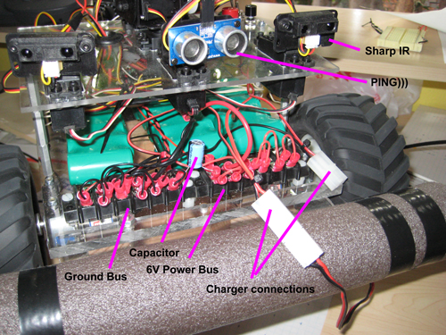
- Ping))) ultrasonic sensor mounted on servo for forward view
- Sharp IR Rangefinder mounted on servos for sides and rear view
- Each servo can be trimmed with a #define to get it perfectly centered
- Airtronics 6 channel radio and receiver for manual control. R/C receiver connected to Axon input ports.
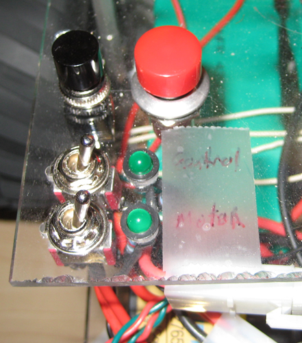
- Push buttons
- Large red one for reset
- Smaller black one for general purpose debugging
- Pulled low by external resisters
- Pulled high by button contact
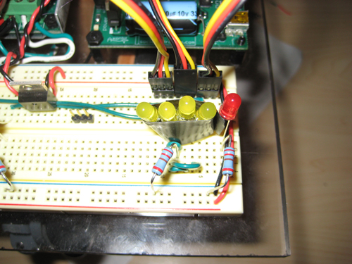
- LEDs (red) for visual debugging of object detection for front and sides (see Map on Software page)
- LEDs (yellow) for visual debugging of Finite State Machine (see FSM on Software page)
Power
- Common ground bus
- Electronics: 6v 2800mAH NiCad
- Unregulated 6v bus powers Axon
- 5v regulated power to servos and sensors via Axon
- 5v regulated provided to breadboard via 7805
- 470uF capacitor between unregulated bus and ground bus to help eliminate voltage fluctuation from servo and sensor use
- Drive motors: 12v (2x6v 2800mAH NiCad in series)
- Separate power switches and indicator LEDs for electronics and motors.
- Power switches are DPST to switch batteries between robot and charger connections
[Next] [Back to index]
|
|
